I have been wanting a soldering station for a long time, or rather a soldering iron with thermal stabilization. We have such soldering irons cost from 3500r, of course it’s expensive and it’s a pity to give that kind of money. But the soldering irons themselves are sold from the stations and they cost a penny. I bought myself the simplest soldering iron for 500r LUT0035, there is nothing about this model on the Internet, only 24V 48V is indicated on the soldering iron label. Brought him home and began to be wiser. First of all, I determined the parameters for my soldering station:
– Temperature control 180-360C
- Current consumption limit for a soldering iron
- Ability to put the soldering iron into standby mode
Defined the parameters and moved on to the schematic
I decided to collect everything on the PWM TL494, it has everything you need: two error comparators and duty cycle adjustment through the 4th DT leg. I already spread the circuit, calculated almost the entire harness around the TL494 and it turned out that it would not be enough for me. The soldering iron I purchased uses a thermocouple instead of a thermistor to detect temperature, and I had to add a voltage amplifier on an additional LM358 op amp. As a result, this is the scheme
There is nothing special in the scheme. A voltage of about 0.025V at 350C is taken from the Thermocouple and multiplied by an amplifier on the LM358 by about 140 times and divided in half by the divider R6R16
Using the variable resistor R8, the desired threshold voltage is set on the 2nd leg of the error comporator, which is approximately 1.75V. Until the potentials between the first and second legs are equal, the PWM will simulate pulses on the control transistor T1. Transistor took IRF630
Button S1 is installed on the lever-stand for the soldering iron, when the button is closed, the pulse width is limited and the current consumption drops by about two, which saves the life of the soldering iron
R12R13 divider that determines the current consumption, is set to a voltage of 0.2V, which, with a shunt of 0.1 Ohm, maintains a current of approximately 2A. I wanted to limit the current in order to save the resource of the soldering iron and transformer
I took the transformer with two serial windings of 17V each with a common point and made it with a filter capacitance of 4700uF.
To indicate heating, I installed a red LED parallel to the heater.
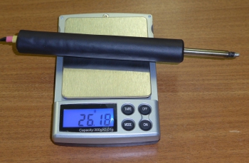
Well, a couple of photos of the soldering station


In principle, everything is on this, everything is elementary. The soldering iron works as it should. Heats up from room temperature to 200C in 85 seconds, to 350C in about 215 seconds
I tried to melt refractory solder, which the 25W mains soldering iron could not take. The station melted without problems, massive tracks and parts of the KU202 type in an iron case are easily soldered
In general, I was satisfied with the homemade soldering station. The only thing that does not suit the soldering iron tip, you need to buy something convenient

Download PCB
Read
With uv. Admin check
The soldering station is built on Hakko T12 cartridges. It has two soldering irons of 70 watts each, a smoke extractor hood, power supplies for external consumers. The budget was about $10-15.
The beginning of the epic was a few months ago when the Hakko T12-KU sting bought for testing arrived. The soldering iron "" assembled for testing turned out to be quite convenient, and the tip cartridge itself pleased with its work. Another more massive tip was ordered, and I decided to make a complete soldering station.
Soldering station features:
Two 70W soldering irons controlled by separate channels. When desoldering parts, it is often more convenient to use two soldering irons at the same time. And during installation, you don’t have to waste time changing the sting. Plus, in my soldering iron design, tip replacement is not provided, for those who want to have replaceable tips, you need to put a purchased pen as one of the soldering irons.
Hood with filter. I don’t particularly want to breathe flux and solder, and as a rule there is no extra space on the table, but here I replaced two with one block.
24V power supply with a separate switch, you can connect a drill or other consumers. In addition, space is also saved, since there is no need to keep the power supply for the drill or constantly reconfigure the laboratory power supply.
Power supply 5v, two USB connectors, for powering the devices themselves. Lately, I’ve soldered mini USB connectors to all boards powered by 5v as power, or for very small boards I throw a cord with a USB connector at the end.
Warning
First, a few warnings.
First.
In the absence of high-quality land, I highly do not recommend using a unit built on the basis of a computer power supply to power soldering irons. Those. it is not advisable to use them in old houses where there is no centralized ground bus. It is also impossible to use central heating pipes as grounding, since now pipes are being massively replaced with plastic pipes in apartments and one cannot be sure of the electrical connection of the battery to the ground.
If you assume the possibility of using a soldering station in the absence of high-quality grounding, then the power supply should be built on the basis of a classic transformer. (Temperature controller circuits do not require a stabilized power source, the only thing is that the voltage should be in the range from 19 to 24 V, otherwise the power of the soldering iron will drop significantly. That is, after the transformer, you can just use a rectifier with a capacitor filter)
Second.
I didn't ground the sting. I suppose when soldering especially sensitive elements, just throw a wire with a crocodile on the sting. If you often solder low-power field-effect transistors and other elements that are especially sensitive to breakdown, then I recommend laying the ground immediately. For safety reasons, the only tip, like the bracelet, should be grounded through a resistor of more than 100 kOhm (recommended through a 1 MΩ resistor).
Third.
As they say, not all yogurts are created equal.
The second sting, bought for $2.76, has noticeable flaws.
I will list the problems in ascending order.
1. When the regulator is operating, sounds are heard from the sting, clicks when the heating cycles are turned on. Most likely, when filling the heater, voids remained, how this will affect durability is not clear.
2. Thermocouple reading too low. If you have such a sting to be used together with normal ones, you will have to constantly recalibrate, the mixture is quite large, about 100g. And for an analog control circuit, recalibration is not a trivial task.
3. The most important drawback. When current flows, the cold junction of the thermocouple seems to heat up, which disrupts the normal operation of the regulator.
I give oscillograms of the regulator with an old sting (it cost about $ 4) and a new one.

With the old sting, the regulator functions normally, the heating cycle and a long pause until the dialed temperature drops to the threshold.

The $2.76 sting is drastically different in behavior. As I assume, the cold junction is heated by the current flowing during heating. And after the heating cycle, when measuring the temperature, an error occurs and the circuit again goes into heating until the temperature of the hot part exceeds the temperature by which the cold junction is heated by the flowing current. After a bunch of heating cycles, the threshold is still exceeded and the regulator goes into a long pause. The cold junction cools down quickly (less than 100ms) and the temperature is measured close to the correct one. As a result, the heating cycle actually lengthens and we get tip temperature fluctuations; for a relatively massive tip at the end, they turned out to be at the level of several degrees, which does not fatally affect the operation. I find it difficult to say how such stings will work with PID controllers, but I think the results will be more deplorable and it will not work to achieve stable operation of the controller.
Main unit
The soldering station is based on an ATX power supply with a 12cm fan. I took such a terry Chinese for alteration. The declared power does not correspond to the filling at all, in fact, a block of 200 watts. But for our purposes, the consumption at the peak of two soldering irons will not exceed 140 watts.

From the top I placed two temperature controllers, separately for each soldering iron. And three switches allow you to separately turn on each soldering iron and an external 24v load. The general inclusion of the unit was left on the standard switch of the ATX unit. The power cable is also connected to the standard connector. Additionally, he brought out 24v power connectors and a USB block for connecting a 5v load.

12cm fan in addition to blowing the block, I use it to extract smoke. To increase the airflow, in addition to the fan inside the case, another fan is installed on the outside. It is advisable to use fans with a power of more than 4W. I got a 12cm 220V 8W fan that I used as an external one. To power the 12v fan, a KREN8B linear stabilizer is used, installed through an insulating gasket on a low-voltage diode radiator. It lowers the voltage of 24V to 12, at the same time, together with the fan, it serves as the load of the power supply at idle. When using 2 powerful 12V fans, it is advisable to use a switching step-down stabilizer (the cost of a finished board for a current of about 2A on Ali is about $ 1). As a last resort, if using a linear regulator, mount it on a separate heatsink. On the front of the external fan there is a grid from the power supply fan, on top of which there is an air filter. I used a piece of a filter from a kitchen hood, it has a sorbent as part of the fiber. You can also look for pure carbon filters, unfortunately I have not yet come across suitable sizes.

I will not dwell on the alteration of the ATX block in detail, since the refinement depends on the model of the power supply. My block was built on the basis of the 3845 chip. I removed all the elements of non-12V channels and all the elements of regular filters and secondary power capacitors. Soldered a new filter using higher voltage capacitors. I was lucky that at the maximum the unit gave out 29v, and to get 24v I only had to pick up the resistance of the resistors in the stabilization circuit, and block the voltage protection circuits.

On the rear grill you can see the 24V terminals and the USB bar taken from the old case. The holes were made simply by biting out the elements of the lattice.
Soldering iron design
The design was considered in the previous article. Now I will show the manufacturing steps again and in more detail.
Connections of wires on twisting and heat shrinkage.

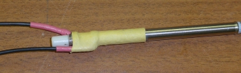


And also, relative to the last time, I somewhat changed the gluing of the paper. This time, I made the increase in the area of the layers gradual, which facilitated gluing.

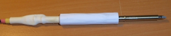


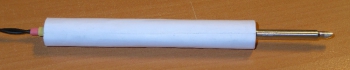
Shrink the heat shrink on top.

Behind to increase rigidity filled with glue.
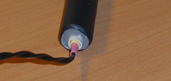
The soldering iron handle is light 26 gr. The distance from the sting is not large, only 4.5 cm.
This design can be used for at least a second soldering iron, for example, making it based on a T12-K or T12-KF tip, which are convenient for desoldering components and microcircuits.
I also met this option on the network: a person soldered wires to contacts, and made a handle from wood.
Temperature controller circuit
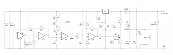
This time I made a circuit based on the LM324. (a circuit based on the LM358 is shown last time).
The Chinese version of the circuit taken as a basis should also be workable, the only thing you need to do is put a protective diode of the 1N4148 type in parallel with the capacitor C4, as in the circuit on the LM358, and the field-effect transistor must have an allowed gate voltage of more than 25 V.

The main difference between this circuit and the circuit on the LM358 is that the voltage from the thermocouple is first amplified, and only then it is applied to the comparator. My schematic is a compilation of a previous LM358 device and a Chinese LM324 schematic.
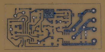
I drew the board in Sprint-Layout version 5. Variable resistor VSP4-1 0.5W, SMD resistors and ceramic capacitors of size 0805, except for R3 of size 2512 and R8 of size 1206, capacitor C7 of size B. The layout of the board is not perfect, but I needed something in size and fit, it coincided with the previous board. Diode D3 serves to protect against incorrect switching on and, in principle, it is not needed if the board is not used autonomously, but in the process of debugging I managed to turn on the board incorrectly in polarity, as a result, after a few seconds, capacitor C5 pulled, and the rest of the board remained intact. Resistor R3 can be replaced with a simple jumper. Resistors R1 and R2, together with a trimmer resistor, determine the range of temperature adjustment, unfortunately the zero drift spread of the operational amplifier does not allow you to accurately select the values of these resistors. My adjustment range is set from 200 to 400 degrees.

The board was made on a two-sided textolite, one of the sides is used underground. Jumpers are soldered into the contacts indicated on the diagram as with metallization, the rest are countersunk. But the board can also be made using a one-sided textolite, then jumpers are thrown from all points indicated by metallization with wires to a point located next to the negative terminal of the C5 electrolyte (it is advisable to make changes to the board by adding additional sites there). I cut the board to the right size after etching the drilling and tinning, because at the edges where I cut with scissors, the foil is deformed and does not clean well.
After desoldering the SMD parts, I washed the board, and only then unsoldered the variable and trimmer resistors, as well as the DIP parts with wires. This allows you to be less limited in the choice of fluxes when soldering SMD.

I solder the rest of the parts and wires using alcohol rosin or, more recently, no-clean flux. (Due to problems with the sting during debugging and have not yet understood the reasons, I tortured the board with soldering a little.)

In general, the circuit on the LM324 works a little better than on the LM358, although the differences are not very noticeable when soldering. The circuit on the LM358, when approaching the stabilization temperature, lights up with an LED for about a second, i.e. approach occurs smoothly with a drop in power delivered to the heater near the stabilization temperature. The circuit on the LM324 enters the stabilization mode more sharply almost immediately, switching to a slow flashing of the LED. Which circuit to choose for implementation should rather determine which parts are at hand, as I said when soldering, I did not notice much difference, although the circuit on the LM324 behaves better.
Plans
Or what he wanted to do and has not yet realized, as they say, there is nothing more permanent in the world than what has been done temporarily.
I'm thinking of putting soldering iron connectors. So that you can make more soldering irons for other tips and, if necessary, change the connected soldering irons. Now there are two mini-jacks on the case, but I am afraid to use them for a current of three amperes.
Put a fuse on external 24V connectors and possibly also for USB outputs.
Well, you need to look for how to replace the old exhaust filter, otherwise it is already dirty, and the air passes with difficulty.
It would also be nice to make some kind of new stand for both soldering irons.
It is necessary to install a small visor on the fan to direct the air flow and improve the suction of smoke.
As a continuation of the idea of a visor, I am thinking of attaching a magnifying glass with illumination there, but this is completely from distant plans.
List of radio elements
| Designation | Type | Denomination | Quantity | Note | Shop | My notepad |
|---|---|---|---|---|---|---|
| U1 | Operational amplifier | LM324 | 1 | To notepad | ||
| U2 | Linear Regulator | LM317 | 1 | To notepad | ||
| Q1 | bipolar transistor | 2N2222A | 1 | To notepad | ||
| Q2 | MOSFET transistor | AO4407A | 1 | To notepad | ||
| D1, D2 | rectifier diode | 1N4148 | 2 | To notepad | ||
| D3 | rectifier diode | 1N4007 | 1 | To notepad | ||
| C1 | Capacitor | 2.2 nF | 1 | To notepad | ||
| C2, C4, C6 | Capacitor | 0.1uF | 3 | To notepad | ||
| C3 | Capacitor | 1 uF | 1 | To notepad | ||
| C5 | Capacitor | 220uF X 35V | 1 | To notepad | ||
| C7 | Capacitor | 10uF X 16V | 1 | To notepad | ||
| C8 | Capacitor | 0.33uF | 1 | To notepad | ||
| R1 | Resistor | 8.2 kOhm | 1 | To notepad | ||
| R2 | Resistor | 1.5 kOhm | 1 | To notepad | ||
| R3 | Resistor | 75 ohm | 1 | To notepad | ||
| R4 | Resistor | 120 kOhm | 1 | To notepad | ||
| R5, R6 | Resistor |
Soldering station - do it yourself
Soldering Station : simple circuit, accessible radio components, accessible to beginner radio amateurs
Hello, dear readers of the site.
Today, I will tell you how to independently make a soldering station from available radio components. This design is available for repetition by both experienced and novice radio amateurs.

For quality soldering, their designs, at home, it is required to set the exact temperature of the soldering iron tip. This is one of the most important parameters for a soldering iron. The temperature of the tip should be lower than the combustion temperature of rosin and higher than the temperature of its boiling and melting of tin.
Radio amateurs If you have a low-voltage electric soldering iron with a built-in thermocouple and a four-wire cable for connecting to a temperature control device, I recommend making a simple tip temperature stabilizer. I chose a soldering iron for this purpose, from a soldering station - HAKKO - 907.

About soldering iron tip temperature:
Tip temperature - determines the quality of soldering. The temperature, as a rule, is regulated by the melting of rosin .... It should boil, but not burn. On the tip of a well-adjusted soldering iron, rosin boils, but does not burn. Boiling rosin - smells good, evaporates quickly, but does not leave burnt black residues on the sting.
Some details of the soldering station:
1.
Output to working temp. – 225deg.- 50sec.
2.
Temp support (interval between on and off) - 4 degrees.
3.
The set adjustment scale is 26-320 degrees (if the regulator is set to a minimum, the soldering iron cools down to room temperature and turns off)
4.
Calibration of the thermocouple of the soldering iron in comparison with the readings of the multimeter 3-4 deg.
5.
Soldering iron 24v / 50w - HAKKO 907, with replaceable tips (practically you can insert any - copper, ceramic or eternal)

The device uses widely used components.
There are no restrictions on replacing the low-signal part of the circuit.
As a temperature meter (indicator), I used the ICL7107 chip (KR572PV2A) and seven-segment indicators - SA04-11 (Red with a common anode)

It is better to use power elements with voltage and current tolerances corresponding to the supply voltage and power of the consumer - the soldering iron heater (50 W).
Download PCB files (in SPL.6 format):
(69.0 KiB, 6,284 hits)
(72.0 KiB, 4,970 hits)
I have long dreamed of a soldering station, I wanted to go and buy it - but somehow I could not afford it. And I decided to do it myself. Bought a hair dryer Luckey-702, and began to slowly collect according to the diagram below. Why did you choose this circuit? Since I saw a photo of finished stations on it and decided that it was 100% working.
Schematic diagram of a homemade soldering station
The circuit is simple and works pretty well, but there is a nuance - it is very sensitive to interference, so it is advisable to hang more ceramics in the microcontroller power circuit. And, if possible, make a board with a triac and an optocoupler on a separate printed circuit board. But I didn’t do that, to save fiberglass. The circuit itself, firmware and signet are attached in the archive, only firmware for the indicator with a common cathode. Fuse for MK Atmega8 in the photo below.

First, disassemble your hair dryer and determine what voltage your motor is on, then connect all the wires to the board except for the heater (the polarity of the thermocouple can be determined by connecting the tester). Approximate pinout of hair dryer wires Luckey 702 in the photo below, but I recommend disassembling your hair dryer and seeing what goes where, you know - the Chinese, they are!

Then apply power to the board and use a variable resistor R5 to adjust the indicator readings to room temperature, then solder the resistor to R35 and adjust the motor supply voltage with a trimmer R34. And if you have it at 24 volts, then adjust 24 volts. And after that, measure the voltage at the 28th leg of the MK - it should be 0.9 volts, if this is not the case, recalculate the R37 / R36 divider (for a 24 volt motor, the resistance ratio is 25/1, I have 1 kOhm and 25 kOhm), the voltage is 28 leg 0.4 volts - minimum speed, 0.9 volts maximum speed. After that, you can connect the heater and, if necessary, adjust the temperature with trimmer R5.

A little about management. There are three buttons for control: T +, T-, M. The first two change the temperature, pressing the button once, the value changes by 1 degree, if you hold it, the values \u200b\u200bbegin to change rapidly. The M button - memory allows you to remember three temperature values, the standard is 200, 250 and 300 degrees, but you can change them as you like. To do this, press the M button and hold until you hear the beeper signal twice in a row, then you can use the T + and T- buttons to change the temperature.

The firmware has a function for cooling the hair dryer, putting the hair dryer on the stand, it starts to cool with a motor, while the heater turns off and the motor does not turn off until it cools down to 50 degrees. When the hair dryer is on the stand, when it is cold or the engine speed is less than the normal allowable (on the 28th leg it is less than 0.4 volts) - there will be three dashes on the display.

The stand should be with a magnet, preferably stronger or neodymium (from a hard drive). Since the hair dryer has a reed switch that puts the hair dryer in cooling mode when it is on the stand. I haven't made the stand yet.

The hair dryer can be stopped in two ways - by placing it on a stand or by twisting the motor speed to zero. Below is a photo of my finished soldering station.

Video of the soldering station
In general, the scheme, as expected, is quite sensible - you can safely repeat it. Sincerely, AVG.
Discuss the article DIAGRAM OF THE SOLDERING STATION
I have long wanted to buy a station, but due to financial problems, the opportunity did not arise and after a little thought I decided - can it be done by hand?
I rummaged a little on the net and found this video https://www.youtube.com/watch?v=wzGbTwlyZxo. The station is just what I need - microcontroller control, data output to the 16x2 LCD display, on which it is displayed.

The top line - the set temperature of the soldering iron and the current temperature on it, the data is updated several times per second (0-480gr)
The bottom line - the set temperature of the hair dryer, the current temperature on it (0-480g), as well as the rotation speed of the fan built into the hair dryer (0-99)


Board and Schematic
You can download the printed circuit board (+ diagram and firmware), everything is original, like the author's.
A few tips for those who are too lazy to watch videos (although I explained everything in some detail in them)
The dimensions of the printed circuit board are already set, there is no need to mirror either. It is advisable to replace the terminals through which the controls are connected to the board, that is, instead of the terminals, use the usual method - take the wires and solder them into the corresponding holes on the board.
During etching, it is MANDATORY to check the sections of the board with the template, since in some places the pins of the SMD components can form a short circuit, all this is clearly visible in the photo

The ATMEGA328 type MK is the same microcontroller that costs a penny in China on programmer boards with an arduino uno kit, but with MK you will need either a home-made programmer or a native arduino uno, as well as a 16 MHz quartz resonator.

MK is fully responsible for the control and output of data on the LCD display. The control of the station is quite simple - 3 variable resistors per 10 kOhm (the most common, mono - 0.25 or 0.5 watts) are the first responsible for the temperature of the soldering iron, the second is the vein, the third increases or decreases the speed of the cooler built into the hair dryer.


The soldering iron is controlled by a powerful field-effect transistor, through which a current of up to 2 Amperes will flow, therefore it will heat up, the triac will also heat up - it, together with a transistor and a 12-volt stabilizer, was brought to a common heat sink by wires, additionally insulated the cases of these components from the radiator.


Be sure to take 3mm LEDs with low consumption (20mA) due to the use of more powerful 5mm LEDs (70mA), the hair dryer did not work for me, or rather, there was no heating. The reason is that the LED on the board and the LED that is built into the optocoupler (it actually controls the entire heating unit of the hair dryer) are connected in series and there was simply not enough power for the LED in the optocoupler to light up.


soldering iron
I myself took a Ya Xun soldering iron for stations of this type 40 watts with a durable tip. The plug has 5 pins (contact holes), the pinout of the plug is below

Keep in mind that the photo shows the pinout of the plug, which is on the soldering iron itself,
The soldering iron has a built-in thermocouple, the data from which is received and decoded by the station itself. You DO need a soldering iron with a thermocouple, not a thermistor as a temperature sensor.


The thermocouple has polarity, if the thermocouple is connected incorrectly, the soldering iron will reach the maximum temperature after turning on and become uncontrollable.

In principle, the power can be from 350 to 700 watts, I advise no more than 400 watts,
more than enough for any need. The hair dryer also has a built-in thermocouple as a temperature sensor. The hair dryer must be with a built-in cooler. It has an 8-pin socket, the pinout of the socket on the hair dryer is shown below.


Inside the hair dryer there is a 220-volt heater itself, a thermocouple, a fan and a reed switch, the latter can be thrown out immediately, it is not needed in this project.
The heater has no polarity, but the thermocouple and the cooler do, so observe the polarity of the connection, otherwise the motor will not spin, and the heater will reach the maximum temperature and become uncontrollable.
power unit
Any (preferably a stabilized adapter) 24 volts minimum 2 amps, advice - 4-5 amps. Universal chargers for laptops are perfect, in which it is possible to adjust the output voltage of 12 to 24 Volts, protection against short circuits and a stabilized output - but it costs a penny, I chose this one myself.

You can also use a low-power power supply for 24 Volt LED strips, available with a current of 1 Ampere or more.

You can also slightly modify the electronic transformer (as the most budget option) and implement it in the circuit, I explained in more detail about the power supplies at the end of the video (part 1)
You can also use a transformer power supply - it may not be stabilized, but I repeat - it is desirable to have stabilization.
Mounting and housing
The case is from a Chinese radio, the 16x2 display fits perfectly to it, all controls are installed on a separate plastic sheet and docked to the bottom of the radio.


The main power components are reinforced on the heat sink, through additional insulating gaskets and plastic washers. The heat sink is taken from a non-working uninterruptible power supply.


It heats up, but only after long work with a hair dryer at high power, but all this is tolerable, by the way - the board provides an additional 12 volt output for connecting a cooper, so that you can blow off the radiator if you need it.


Setting
In principle, to set up, you need either a thermometer or a tester with a thermocouple and the ability to measure temperature.


First you need to set a certain temperature on the soldering iron (for example, 400g), then press the thermocouple to the soldering iron tip in order to understand the real temperature on the tip, and then simply using the trimming resistor on the board (slow rotation) we achieve to compare the actual temperature on the soldering iron (which is displayed) with the one shown by the thermometer.